Guides/Gearbox Design
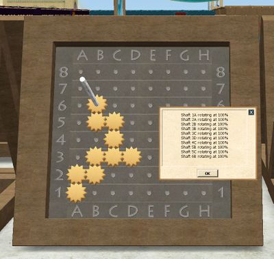
Gearboxes are used in a number of the more advanced buildings, normally to add a unique cost for each construction. Each gearbox takes an input shaft rotating and converts it via a gear train into up to 3 outputs. The process of designing a gearbox is to figure out which ratios are needed and to implement those ratios in the form of positioning various sizes of connected gears on a Gearbox Assembly Table.
Gearbox requirements are denoted by one or more ranges (like 'A380-A453', or 'B60-72 D350-386'). Any gearbox which has a gear in the top row which is turning with a speed in that range will be acceptable. Gears on the top row are called 'outputs'.
For example, if you need a gearbox with range E150-E186, this means the gearbox needs to have a gear at position E8 turning at between 150% and 186%
Note, gearboxes can have a maximum of three gears on the top row. There are no buildings which need more than 3 outputs.
Gearbox design
Gears
There are 5 gear sizes available, measured by their number of teeth (or relative number of teeth):
| Gear Size | Item | Metal cost | Wax cost | CC cost (student) | CC cost (master) |
|---|---|---|---|---|---|
| 1 | Spacer | 0 | 0 | 0 | 0 |
| 3 | Small Gear | 2 | 2 | 1 | 0.8 (batch of 10) |
| 4 | Small Gear | 2 | 2 | 1 | 0.8 (batch of 10) |
| 5 | Medium Gear | 15 | 15 | 5 | 10 |
| 6 | Medium Gear | 15 | 15 | 5 | 10 |
| 7 | Large Gear | 100 | 100 | N/A | 40 |
The type of metal depends upon the rotation speed of each gear. The following ratios have been tested:
| Speed | Metal | Notes |
|---|---|---|
| 1-48 | Gold | |
| 49-95 | Copper | |
| 96-143 | Aluminum | |
| 144-190 | Iron | |
| 191-238 | Platinum | |
| 239-285 | Tin | |
| 286-333 | Zinc | |
| 334-381 | Silver | |
| 382-428 | Magnesium | |
| 429-476 | Iron | |
| 477-523 | Zinc | |
| 525-571 | Lead | |
| 572-618 | Copper | |
| 619-666 | Antimony | |
| 667-714 | Nickel | |
| 715-760 | Aluminum | |
| 762-807 | Silver | |
| 810-855 | Platinum | |
| 857-904 | Tin | |
| 905-950 | Lead | |
| 952-43439 | Iron |
Constraints
Up to 15 shafts may be placed in the 8x8 grid on the gearbox assembly table. Each shaft may contain up to 3 gears or spacers, and a gearbox may have no more than 30 gears in total (including spacers). There must be at least one gear on the input shaft at 1A, and a connected set of gears leading to between 1 and 3 shafts on the output row (8A-8H, at the top). The output row 8 may contain a maximum of three occupied cells, presumably to be used as outputs - no extra transfer gear locations.
Meshing
If two shafts are near each other, a gear on one shaft may mesh with a gear on the nearby shaft. This depends upon the sizes of the gears involved, and how far apart the shafts are.
- Adjacent: gear sizes must sum to 6 (the only possible combination is 3 meshing with 3)
- Diagonal: gear sizes must sum to 8 (4 meshes with 4, or 5 with 3)
- 2 steps apart: gear sizes must sum to 11 (6 meshes with 5, or 7 with 4)
- "Knight's move", 2 steps away then 1 sideways: sizes must sum to 12 (6 with 6, or 7 with 5)
To mesh, gears must also be on the same layer, i.e. both being the first gears on their respective shafts, both second, or both third. If the sum of sizes of gears between a pair of shafts is greater than needed to mesh, they are too close and you must remove one. This includes spacers, which count as greater than 1 (but less than 2) for meshing purposes. For example, you can not put a spacer adjacent to a 5 or 6 gear, and you can not put a spacer either adjacent or diagonal to a 7 gear.
To minimize conflicts with adjacent shafts, generally put your small gears on the bottom layer with your medium and large gears on the second or third layer.
Standard Gearbox Notation
- / meshes with.
example: 5/3 or (5/3) or 53 - a size 5 gear that meshes with a size 3 gear.
- * shares a shaft
   example: (5/3) * (7/4) - a size 5 gear meshing with a size 3 gear. On the same shaft
   as the size 3 gear is a size 7 gear, which meshes with a size 4 gear.
   example: (7/4) * (5/3) - the 7 still meshes with the 4, and the 5 with the three,
   but this time, the 4 and the 5 share a shaft. Note that this results in the same
   output as the previous example - as long as all the same gears mesh, you can move
   it around in the chain without affecting the output speed.
This notation gives a standardised way of representing the gearbox table. To get from the factored notation to the actual rotation rate, just multiply out the fractions. For example, the (5/3) * (7/4) combination above would give (5 * 7) / (3 * 4) = 35/12 = 2.91666666 (which, as a percentage, rounds to 292%)
When designing a gearbox it's often useful to use factored notation, (6/5 * 5/3) * 5/3 = 655/533 (meaning 6x5x5 divided by 5x3x3) rather than 333%, as it's much easier to visualize the common elements when using the factored notation.
Rate in Gear Trains
Each shaft has a rotation rate, based on the 1A input shaft being 100%. In a properly designed gearbox, you can trace any output back to the input via a single chain of meshed gears between shafts. The rotation of the output is driven by the rotation of the second-last shaft, and so on back to 1A.
If the meshed gears between a pair of shafts are the same size, then both shafts rotate at the same rate. If they are not the same size, the shaft with the larger gear rotates slower. For example, suppose shaft 1A has a 3-gear (with 3 teeth), meshing with a 5-gear on shaft 2B. Every 5 rotations of shaft 1A will pass 15 teeth through where the gears mesh. Those 15 teeth are only 3 rotations of a 5-gear, so shaft 2B will rotate 3 times for every 5 rotations of 1A. That is, a rotation rate of (3/5) or 60%.
The same principle can be used many times in a row by using the 3 different layers available. A 3-gear on 1A can mesh with a 5-gear on 2B on the bottom layer, meaning that 2B rotates at 60%. Then we can put a 3-gear on the second layer of 2B, meshing with a 5-gear on the second layer of 3C (with a 1-spacer on the bottom layer). So 3C rotates at (3/5) of 2B, which is in turn (3/5) of shaft 1A. The final rotation rate of 3C is thus (3/5)*(3/5) = 36%.
Putting it Together
The need for gears to mesh, together with how they determine rotation, means that any output can be expressed as a product of a limited set of fractions. The earlier example is (3/5)*(3/5), expressing that going from 1A to 2B we mesh a 3-gear with a 5-gear (in that order), and the same from 2B to 3C. To build a gearbox with outputs in a desired range, you just need to find a sequence of fractions that multiply to give the right numbers. Much of the work has been done already, with a list of common Gearbox Ratios that may be useful.
3/3 and 4/4 just carry a given rotation rate from shaft to shaft, and are comparatively cheap since gears of size 3 and 4 are small gears. Many designed gearboxes contain chains of gears -3-3-3 or -4-4-4 carrying a given ratio to the required output shaft.
3/5 and 5/3 are the next cheapest, since size 5 is a medium gear.
5/6 and 6/5 come next in cost order, with both 5 and 6 being medium gears.
3/6 and 6/3 are shorthand, with an implicit 5-gear in the middle since 3-gears and 6-gears cannot mesh directly. Hence this ratio costs 2 mediums and a small.
4/7 and 7/4 are much more expensive: a 7-gear is a Large gear costing 120 iron and requiring the master casting box.
More expensive still are the shorthand ratios of 3/7, 7/3, 6/7 and 7/6, all of which have an implicit 5-gear in the middle to allow the others to mesh. Finally there is 6/4 which has an implicit 5 and 7 in the middle. Fortunately these ratios are almost never needed.
The relative cost of the various gear ratios ignores the small gears and assumes that a large gear costs 5 times as much as a medium gear. A combination like (3/5*5/6) that has a shared gear will be a bit cheaper. Note that every change in speed requires a medium or large gear.
- Cost of 1 - 3/5 and 5/3
- Cost of 2 - 5/6 and 6/5
- Cost of 6 - 4/7 and 7/4 (or 5/7 and 7/5)
Example, two outputs
Still not sure how to design your own gearbox? Here is an example, with step-by-step reasoning on how to arrive at a solution.
Find ratios
Let's say we have a requirement for a 2-output Gearbox 'A55-70 D240-280'. The first thing you should do is look at the list of Gearbox Ratios. The goal is to find the cheapest ratios that are within the required intervals.
- It seems that we have a very cheap way to make the first output with a rotation speed of 60%. This can be made with just a (3/5) conversion!
- For the second output, 278 seems to be the cheapest ratio with a (5/3)*(5/3).
Plan a fork point
To obtain two different outputs, we will need to make a route of meshing gears from 1A to 8A, and another route from 1A to 8D. We could perhaps make two completely separate routes in different "layers", but it is smarter to begin using the same route and then *fork* the route at some point.
Forking close to the end will cost fewer gears than if we fork early, but if the conversion ratios are more complicated, we might need to fork earlier to have room for the conversions. We begin by making a guess at the fork point, which should be located pretty close to the outputs. Let's go with 6C, and adjust it when we run into trouble.
Place the conversions
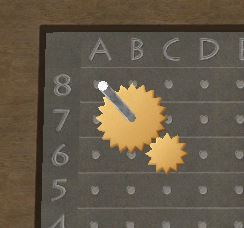
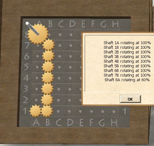
Placing a 3-tooth on 6C and a 5-tooth on 7B, the first conversion (3/5) takes us one diagonal step away from the fork point:
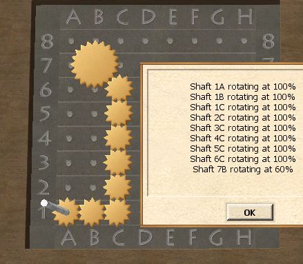
Completing the route down to 1A assures us that the conversion to 60% works:
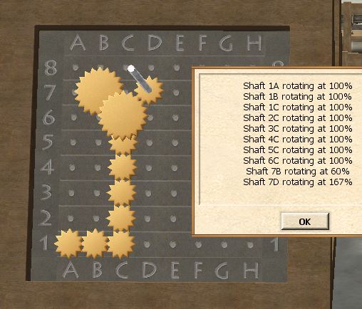
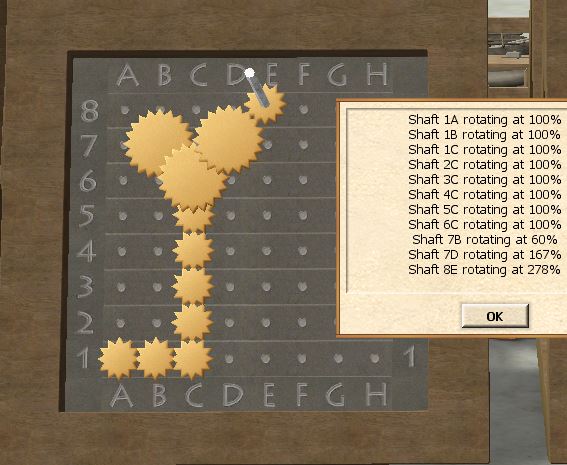
To get a (5/3)-conversion from the fork point, we need to use another layer. We can place a 5-tooth on top of the gear already placed at 6C, but a 3-tooth on 7D will not mesh with 6C, unless we raise it to the second layer! That's what the spacers are for, so make sure to place one on 7D before adding the 3-tooth. If done correctly, 7D should now be rotating:
To make the last (5/3)-conversion, we can use the third layer, and place a 5-tooth on top of 7D, followed by two spacers and one 3-tooth on 8E. We finally have shafts rotating at the desired speeds!
Adjusting the forkpoint
Now begins the tricky part. Ideally, we would have landed on 8A with the first conversion, or on 8D with the second one. Can we move the fork point to a smarter place?
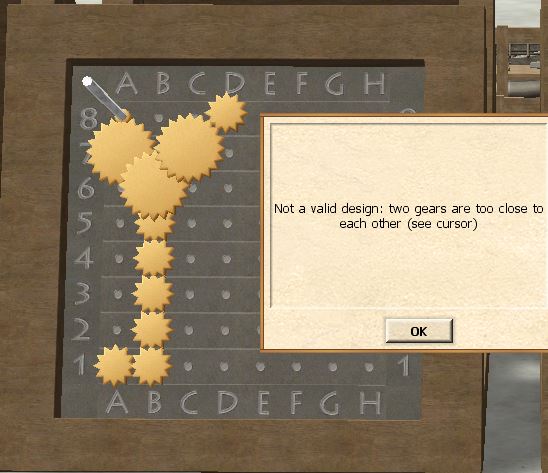
One option would be to fork at 6B instead of 6C - all we need to do is shift the entire design one step to the left! Then the output at 8E shifts to 8D as desired. But we are very cramped for space around 8A, with a 5-tooth at 7A blocking spacers on 8A:
This problem might be solvable by switching layers for the conversions, but let's try another approach first. What happens if we fork at 7B instead? Then the first output lands on 8A as desired.
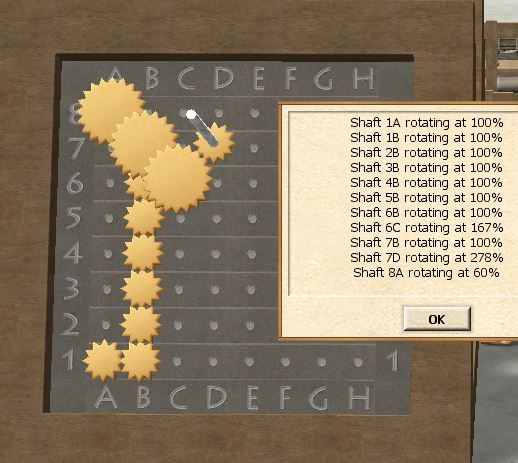
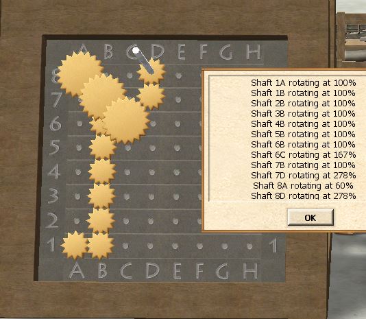
How do we best make two diagonal steps from 7B? To leave as much room around 8D as possible, we decide to go down from 7B to 6C, then up to 7D. Remembering the spacers, we should get this result:
Suddenly we are just one vertical step away from 8D now, with enough room to place 2 spacers and a 3-tooth! Doing so gives our first valid design:
Fine tuning
Since there is a limit on number of gears, and number of shafts, your design might still not be valid at this point. These limits mostly come into play when designing 3-output Gearboxes, but there are some things you should try anyway to see if you can reduce the number of gears:
- Changing the fork point again
- Switching layers of some (or all!) gears
- In the trickiest cases, you may need to revisit the table of Ratios, to see if there are other possibilities.
Let's just look at one possible adjustment to our design. First remove all gears and spacers at 7D and 8D. Then add a 3-tooth, a spacer and another 3-tooth to 7D, and a 3-tooth to 8D. We have removed 3 spacers at the cost of adding one additional 3-tooth.
(This is an example of how to reduce the total number of gears if you are close to the limit, but you should of course avoid adding extra 3-tooths in general, since that increases the number of gears in the cost of the Gearbox.)
Existing Designs
Link your personal build pages here.
